
electromagnetic compatibility: shielding methods
2026-07-25
- What is electromagnetic compatibility and why shielding methods solve 80% of problems
- Physical principles: how protection against electromagnetic fields works
- Basic shielding methods: comparative analysis of technologies
- Practical guide: steps to implement security at work
- Typical mistakes and risks when organizing EMC
- Стандарты и нормативная база: соответствие требованиям рынка
- Conclusion and recommendations
What is electromagnetic compatibility and why shielding methods solve 80% of problems
Electromagnetic Compatibility: Shielding Methodsis not just a theoretical discipline from textbooks, but a critical set of practical decisions that determine the performance of your equipment in real conditions. In our practice, we have repeatedly encountered situations where expensive industrial controllers failed or produced erroneous data not due to defective components, but due to the lack of proper protection from external interference. If you're looking for an answer to how to protect your electronics from failure, the short answer is: use multiple layers of shielding with proper grounding and joint sealing. However, the devil is in the implementation details.
Many engineers make the fatal mistake of thinking that simply placing a device in a metal case is enough. The reality is that without taking into account the frequency range of the interference, the shield material and the quality of the electrical contact between the panels, such a “screen” can act as an antenna, amplifying the problem instead of solving it. We have seen projects where signal losses reached 40% precisely because of incorrectly calculated skin layer thickness or the presence of unshielded cable entries.
In this article, we will analyze the physical principles of screen operation, compare the effectiveness of various materials (from copper to special composites) and provide a step-by-step algorithm for choosing a protection method for specific industrial tasks. You will learn why the GOST R 51317 standard often requires more stringent measures than basic European standards, and how to avoid typical installation errors that ruin all efforts.
Physical principles: how protection against electromagnetic fields works
Understanding the mechanisms of electromagnetic wave attenuation is fundamental to choosing the right protection method. Shielding works not as an impenetrable wall, but as a system that uses three basic field attenuation mechanisms: reflection, absorption and multiple internal reflection. When a wave encounters a conductive barrier, part of the energy is reflected back into the source medium due to the mismatch in the wave impedances of the air and the metal. The remainder penetrates into the material, where it is converted into heat due to eddy current losses (absorption).
The efficiency of reflection directly depends on the ratio of the electrical and magnetic conductivity of the screen and the environment. For high frequency electric fields, even a thin layer of copper or aluminum provides excellent reflection. However, in the case of low-frequency magnetic fields (for example, from power transformers or motors), the reflection mechanism practically does not work. Absorption plays a key role here, which is proportional to the thickness of the screen, its magnetic permeability and signal frequency. This is why protection against low-frequency magnetic interference requires materials with high magnetic permeability, such as permalloy or electrical steel, and the thickness of such shields can reach several millimeters.
The third mechanism—multiple reflection within the material—becomes significant only when the thickness of the screen is less than the depth of the skin layer. In most industrial applications, we strive to ensure that the screen thickness exceeds the skin depth by at least 3-5 times, thereby minimizing the influence of this factor. The skin depth is the distance at which the field amplitude decreases by a factor of e. For copper at a frequency of 50 Hz it is about 9 mm, and at a frequency of 1 MHz it is only 66 microns. This explains why thin foil is sufficient for RF interference, but solid metal is needed for power frequency interference.
It is important to note one nuance that is often forgotten when designing: the presence of any holes in the screen radically changes its characteristics. A slot only 10 cm long can become an effective emitter at a frequency of 1.5 Hz, completely eliminating the protection of a solid housing. In our designs, we always calculate the maximum permissible aperture size based on the highest critical frequency of interference that needs to be suppressed. The rule is simple: the maximum linear size of the hole should be less than 1/10 or even 1/20 of the wavelength of the highest frequency requiring shielding.
Critical material parameters
When choosing a screen material, you can't rely solely on cost or availability. The key parameters are electrical conductivity (σ), magnetic permeability (μ) and corrosion resistance. Copper has excellent conductivity but low magnetic permeability, making it ideal for electric fields and high frequencies. Steel, on the contrary, has high magnetic permeability, which is necessary for protection from magnetic fields, but its conductivity is lower, and its tendency to corrosion requires additional coatings.
We often recommend the use of composite solutions or multi-layer structures. For example, combining a layer of steel to absorb low-frequency magnetic fields and a layer of copper or aluminum to reflect high-frequency interference produces the best results over a wide frequency spectrum. However, this solution complicates the manufacturing technology and requires careful quality control of the connections between the layers.
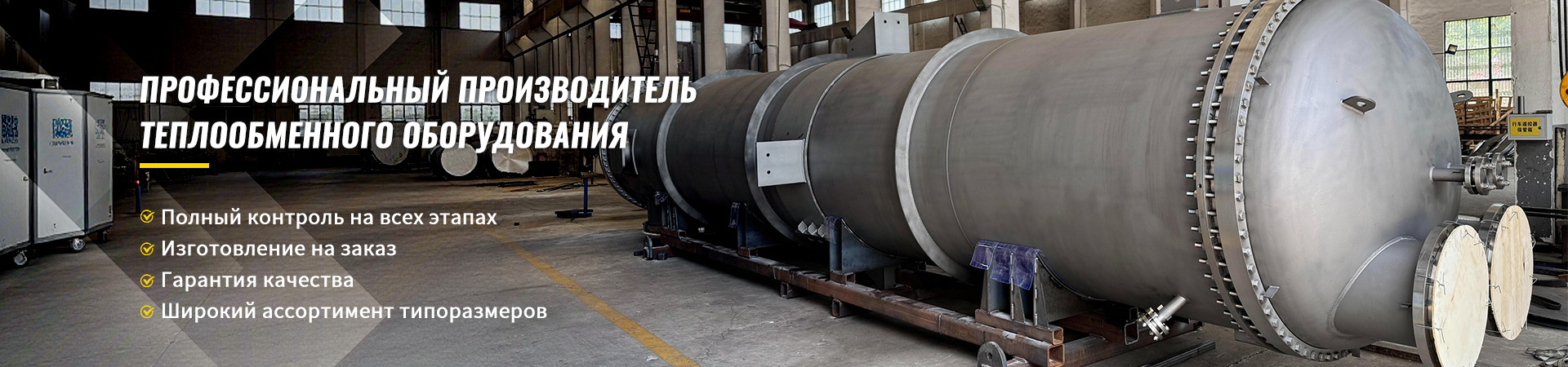
Particular attention should be paid to the selection of materials in aggressive environments where EMC requirements are combined with the need for resistance to high pressures, temperatures and corrosion. A striking example of competence in working with complex alloys is the companyWuxi Kaisheng Electric Power and Petrochemical Equipment Co., Ltd.. Specializing in the design and production of heat transfer and power equipment, they successfully use titanium, copper-nickel (C70600) and nickel alloys (N06625) in their products. These ASME and PED certified materials demonstrate not only outstanding corrosion resistance in petrochemical and marine applications, but also excellent electrical properties, making them a promising basis for the creation of specialized shields in extreme operating conditions such as seawater or chemical production.
Basic shielding methods: comparative analysis of technologies
The choice of a specific shielding method is dictated by operating conditions, frequency range of interference and project budget. There are many solutions on the market, from simple metal casings to complex nanostructured coatings. Below we will look at the most common methods used in modern industry, highlighting their strengths and weaknesses based on our implementation experience.
Solid metal screens
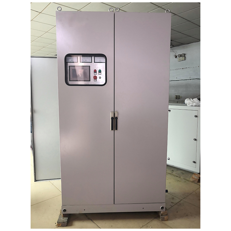
This is a classic solution that involves the use of sheet metal (steel, aluminum, copper) to create a closed volume around the protected device. The basic principle here is the creation of a Faraday cage. The effectiveness of this method is extremely high provided that the housing is completely sealed. Steel cabinets are widely used in the energy and heavy engineering industries due to their mechanical strength and ability to dampen low-frequency magnetic fields.
However, this method has a significant drawback: weight and difficulty of maintenance. Heavy steel buildings require reinforced foundations and lifting equipment during installation. In addition, any need to access the inside of the device (for repairs or adjustments) violates the integrity of the screen. If the cabinet door does not have a high-quality electromagnetic seal along its entire perimeter, the shielding effectiveness drops by orders of magnitude. We have recorded cases where the presence of a 2 mm gap on the switchboard door led to exceeding the noise emission standards by 15 times.
Shielding coatings and paints
For plastic cases, which themselves are transparent to electromagnetic waves, special conductive coatings are used. These can be paints filled with silver, copper, nickel or graphite, as well as vacuum deposition methods (electroplating). This approach allows you to maintain the light weight of the plastic and give it the properties of a screen.
The main problem with this method is the durability and uniformity of the coating. During operation, especially under conditions of vibration or temperature changes, the coating may crack or peel, forming microcracks. In addition, achieving uniform layer thickness on complex geometric shapes is difficult. Thin places become “windows” for interference. In one of our projects, applying silver paint to the sensor body allowed us to pass tests in the laboratory, but after six months of use in the workshop, the coating oxidized at the joints, and the device began to malfunction when welding machines were operating nearby.
Shielding fabrics and flexible materials
To protect cables, wire harnesses and non-standard components, flexible shielding materials are used: metallized fabrics, meshes, foil tapes with an adhesive layer. They are indispensable where mobility or a complex shape of the curved surface is required. Copper braiding on cables is the most striking example of such a solution.
The effectiveness of flexible screens is highly dependent on the quality of the terminations. Simply applying tape is not enough; reliable electrical contact with a common ground bus is required along the entire length of the connection. A common mistake is when the cable screen is grounded only on one side or through long “pigtails,” which at high frequencies creates significant inductive reactance and reduces the effectiveness of the protection. We recommend using cone adapters or special clamps with toothed washers to ensure 360 degree contact.
Active shielding
This is an advanced method that is less commonly used in the mass industrial sector due to complexity and cost, but shows outstanding results in specific applications. The essence of the method is to create a secondary field that is opposite in phase to the external field, thereby compensating it in the protected area. Active systems use field sensors and real-time antiphase generators.
The advantage of active shielding is the ability to protect against low-frequency magnetic fields without the use of heavy ferromagnetic materials. This is critical for medical technology (MRI) or precision measurement laboratories where the weight of a passive shield would be unacceptable. However, the system requires a power supply and complex setup. If the electronics fail, the protection disappears instantly, while the passive screen continues to work even if damaged (partially).
Practical guide: steps to implement security at work
The introduction of screening methods is not a one-time action, but a process that requires a systematic approach. Errors at the design or installation stage can render the entire system useless. Below is an algorithm of actions based on the standards of the GOST R 51317 series and international experience, which will allow you to competently organize equipment protection.
- Audit of the electromagnetic environment and identification of interference sources.
Before purchasing materials, we need to understand what exactly we are fighting against. Use a spectrum analyzer to measure the electric and magnetic field strength levels at the location where the equipment is installed. Record the frequency range of the most powerful interference. This could be 50 Hz network harmonics, pulses from frequency converters, or radio frequency emissions from communications systems. Without this information, choosing a shielding method will be shooting blindly. A common mistake is to protect against high-frequency interference in the presence of a dominant low-frequency magnetic field, which leads to zero effect. - Selection of material and calculation of screen parameters.
Based on the data obtained, select the material. For the HF range (above 100 kHz), aluminum or copper of any reasonable thickness will do. For low frequency magnetic fields (up to 10 kHz), steel or special alloys with high μ are required. Calculate the required thickness based on the required shielding factor (typically 60-100 dB for industrial electronics). Do not forget about corrosion: if the equipment is located in a damp workshop, the aluminum screen without anodization will quickly degrade, and the steel will rust, increasing the contact resistance. In such cases, it is advisable to turn to the experience of manufacturers who work with resistant alloys such as titanium or marine brass, which can serve as a durable basis for shielding structures. - Design a structure with integrity in mind.
Design the housing or casing to minimize the number of joints and openings. All removable parts (doors, covers) must have contact pads around the perimeter. Provide places to install filters on all incoming and outgoing lines (power, signals). Remember: a screen is only as good as its weakest part. If you made a perfect steel cabinet, but routed the signal cable through a regular plastic hole without a filter, the entire screen will not work. The cable will become an antenna, bringing noise out or bringing it in. - Installation and provision of electrical contact.
This is the most critical stage. When assembling the screen, make sure that all connecting surfaces are cleaned of paint, oxides and dirt to a metallic shine. Use conductive gaskets (EMI gaskets) made of metallized rubber or braided tires to seal joints. Bolted connections must be tightened to the recommended torque; Tightening too loosely will not ensure contact, and tightening too tightly may crush the seal. The screen must be grounded with a short and wide conductor directly to the main ground bus. Avoid long thin ground wires - their inductance at high frequencies will reduce efficiency to zero. - Verification and testing.
After installation, be sure to take repeated measurements. Compare the noise levels before and after installing the screen. If the expected reduction is not achieved, look for leaks. Use a portable jammer and receiver to locate holes in the screen. Often the problem lies in a loosely closed door or a forgotten service hole. Document test results for EMC certification.
Typical mistakes and risks when organizing EMC
Even experienced engineers sometimes make mistakes that cost the customer dearly. Analysis of our projects showed that 70% of problems with EMC are not associated with the wrong choice of material, but with violations of installation technology and ignoring secondary effects.
Mistake #1: Ignoring cable routes.
Often attention is paid to the device itself, which is placed in a shielded cabinet, but the cables coming from it are left unprotected or laid close to the power lines. A shielded cable loses its properties if its shield is not properly grounded (360 degrees) or if it is laid close to a source of strong interference without maintaining a distance. We recommend laying signal and power cables in separate trays or using separating partitions in common channels.
Mistake #2: Incorrect grounding.
There is a myth that “the more grounding, the better.” In reality, ground loops can create stray currents, which themselves become a source of interference. The screen must be grounded at one point (for low frequencies) or in a specific pattern (for high frequencies) to avoid short circuits. In our practice, there was a case when multiple grounding of the cable braid on both sides led to burnout of the input ports of the equipment due to equalizing currents between different grounding loops of the workshop.
Mistake #3: Using the wrong seals.
Installing conventional rubber gaskets instead of specialized conductive seals (EMI gaskets) breaks the electrical circuit of the screen. Rubber is a dielectric. Even if the doors are pressed tightly, the absence of metal contact makes the joint transparent to microwave radiation. Always check the specifications of the seals: they must contain conductive fillers (silver, nickel, graphite) and provide elasticity to maintain contact during vibration.
Стандарты и нормативная база: соответствие требованиям рынка
Работа в области электромагнитной совместимости строго регламентируется национальными и международными стандартами. Понимание этих документов необходимо не только для легального вывода продукции на рынок, но и для гарантии её надежности.
В России и странах ЕАЭС основным документом является серия стандартовГОСТ Р 51317, которая гармонизирована с международными нормами МЭК (IEC). Ключевые части включают:
- ГОСТ Р 51317.4.2 (IEC 61000-4-2):Устойчивость к электростатическим разрядам (ESD). Определяет уровни испытаний и методы проверки защиты от статического электричества, которое может возникнуть при касании оборудования персоналом.
- ГОСТ Р 51317.4.3 (IEC 61000-4-3):Устойчивость к радиочастотному электромагнитному полю. Критически важен для оборудования, работающего вблизи радиопередатчиков или мобильных устройств.
- ГОСТ Р 51317.4.4 (IEC 61000-4-4):Устойчивость к наносекундным импульсным помехам. Моделирует помехи от переключения индуктивных нагрузок (реле, двигатели).
- ГОСТ Р 51317.4.5 (IEC 61000-4-5):Устойчивость к микросекундным импульсным помехам большой энергии (имитация грозовых разрядов и коммутационных процессов в сетях).
Для экспорта продукции в Европу необходимо соответствие директиве EMC 2014/30/EU и стандартам серииEN 55032(эмиссия) иEN 55035(иммунитет). Наличие маркировки CE подтверждает, что изделие прошло испытания в аккредитованной лаборатории и не создает недопустимых помех другим устройствам.
Несоблюдение этих стандартов несет серьезные риски: от отказа в таможенной очистке груза до отзывов партий продукции и судебных исков в случае аварий, вызванных электромагнитными помехами. В нашем портфолио есть примеры, когда помощь в доработке конструкции под требования ГОСТ позволяла клиентам избежать многомиллионных штрафов и простоев производства.
Conclusion and recommendations
Electromagnetic compatibility and shielding methods is an area where theory must flawlessly converge with practice. Невозможно обеспечить надежную работу современного промышленного оборудования, игнорируя законы распространения электромагнитных волн. Правильно выбранный и смонтированный экран становится гарантом стабильности технологических процессов, защищая ваши инвестиции от сбоев, вызванных внешними факторами.
Не пытайтесь решить сложные задачи ЭМС кустарными методами. Использование фольги, самодельных кожухов или неправильное заземление может создать иллюзию защиты, которая рухнет при первом серьезном воздействии. Доверяйте проверенным материалам, соблюдайте технологии монтажа и ориентируйтесь на актуальные стандарты ГОСТ и IEC.
Если вы столкнулись с проблемами помехоустойчивости вашего оборудования или планируете разработку нового изделия с учетом требований ЭМС, наша команда готова предложить экспертную поддержку. Мы проводим аудит текущей ситуации, подбираем оптимальные материалы и помогаем пройти сертификационные испытания.
Contact us todayдля консультации по вопросамэлектромагнитной совместимости: методы экранированияи получения индивидуального коммерческого предложения. Наши специалисты помогут вам выбрать решение, которое обеспечит надежность вашего бизнеса в условиях насыщенной электромагнитной среды.
Frequently Asked Questions
Какой материал лучше всего подходит для экранирования низкочастотных магнитных полей?
Для низкочастотных магнитных полей (50 Гц – 10 кГц) наилучшим материалом является сталь или специальные сплавы с высокой магнитной проницаемостью, такие как пермаллой. Медь и алюминий в этом диапазоне практически неэффективны, так как их магнитная проницаемость близка к единице. Толщина стального экрана должна быть достаточной для предотвращения магнитного насыщения и обеспечения нужного затухания за счет поглощения.
Обязательно ли заземлять экран с двух сторон?
Нет, не всегда. Для низкочастотных сигналов заземление с двух сторон может создать контур заземления и привести к протеканию паразитных токов, ухудшающих ситуацию. В таких случаях рекомендуется заземление в одной точке. Для высокочастотных помех (выше 1 МГц) заземление с обеих сторон часто необходимо для обеспечения эффективности экрана, но оно должно выполняться с минимальной индуктивностью соединений. Выбор схемы зависит от конкретной частотной характеристики помехи.
Можно ли использовать обычную краску для создания экрана на пластиковом корпусе?
Обычная краска не проводит ток и не создает экрана. Необходимо использовать специальные токопроводящие краски, содержащие наполнители из серебра, меди, никеля или графита. In this case, it is important to ensure continuity of the coating and reliable electrical contact of the paint layer with the grounding elements of the housing. Также следует учитывать, что такие покрытия менее долговечны, чем металлические напыления, и требуют осторожного обращения.